 Skip to content
 Geotextile flood barrier specifications aren’t marketing bullet points when you’re the officer calculating how many flat-packed pallets fit on a C-130 and whether the crew can assemble a 10-cell wall before the river crests. Every dimension, coating grade, and liner material callout on that sheet has a direct operational consequence. Deployment speed, transport density, and multi-season durability all hang on those numbers. Get one spec wrong and you’re not just over budget—you’re 10 workers and 7 hours into a sandbag operation that should have been a 20-minute loader job.
The failure mode most evaluation reports overlook doesn’t appear in the mesh thickness column. It’s in the geotextile. Woven liner fabrics tear directionally under hydrostatic pressure, opening linear runs that drain the fill and collapse the wall. Non-woven polypropylene liners deform uniformly under the same load—stretching in all directions instead of splitting along a weave line. That single material property is the engineering reason a correctly specified unit delivers the 5-plus-year service life USACE procurement cycles depend on. Miss the baked-on UV treatment in the spec, and even non-woven liners degrade within 18 months of sun exposure. For multi-event inventory planning, that’s the hidden cost multiplier no sandbag comparison chart will show you.
Geotextile Barrier Core Specifications
The point of failure is rarely the mesh—it’s the liner. Non-woven geotextile stretches omnidirectionally under hydrostatic load; woven fabric tears along bias lines. This single material choice determines whether a barrier section lasts one flood season or five.
Zinc-Aluminum Coated (Galfan) Welded Mesh Frame
The structural skeleton of every unit is formed from welded steel wire mesh with a Galfan coating—a zinc-aluminum alloy that delivers approximately three times the corrosion resistance of traditional hot-dip galvanizing in chloride-rich environments. Unlike standard zinc layers, which develop white rust at coating discontinuities, Galfan’s aluminum content forms a stable, self-passivating oxide film that halts underfilm corrosion. For flood defense in brackish or coastal zones, this is not a premium option; it is a minimum spec.
Mesh wire diameters and weld spacing vary by cell size, but the typical configuration uses a 3.0 mm to 4.0 mm wire on a 50 mm × 50 mm grid. The welds themselves are not spot-tacked edges—they are full-resistance welds at every intersection, giving the panel a rigid, lattice-like behavior under lateral fill pressure. This rigidity is what permits stacking without buckling when joining pins are driven through aligned corner loops.
Heavy-Duty Non-Woven Polypropylene Geotextile Liner
The liner is a needle-punched, non-woven geotextile manufactured from UV-stabilized polypropylene fibers. A common manufacturing shortcut is to post-treat a standard woven tarp with a topical UV spray, which weathers away within six months. The correct specification, and the one required to achieve a 5+ year exposed lifespan, is a baked-on UV-resistant coating infused into the polymer melt during fiber extrusion. This treatment prevents rapid loss of tensile strength from photodegradation, which is the dominant failure mode for untreated polypropylene in sustained sunlight.
Under hydrostatic pressure, non-woven fabric stretches evenly in all directions. Woven polypropylene, by contrast, elongates predominantly along the bias (diagonal), creating localized necking “runs” that channel water directly through the liner. A non-woven liner distributes stress across its random fiber matrix, maintaining a continuous filtration grade that keeps fill material inside the cell while bleeding water. This is not a minor textile nuance; in a 48-inch-high wall, a single woven-fabric run can evacuate 15% of the cell’s fill mass in minutes, setting off a cascade of cell collapse.
Standard Cell Sizes and Fill Volume Capacities
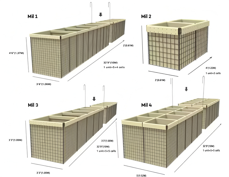
The industry-accepted cell dimensions originate from military-gauge engineering and have been adopted for civilian flood control without alteration. The five standard welded-mesh cell sizes are as follows, with fill volumes calculated assuming level fill and no loss from compaction:
- 39″ × 39″ (990 mm × 990 mm): Approx. 0.91 cubic yards (0.70 m³) of fill per cell. Used for tall perimeter walls where mass is the primary design factor.
- 27″ × 27″ (686 mm × 686 mm): Approx. 0.30 cubic yards (0.23 m³) per cell. The preferred size for rapid-deployment stacks, balancing fill rate with wall height.
- 48″ × 36″ (1219 mm × 914 mm): Approx. 1.0 cubic yard (0.76 m³). Typically deployed as a single-row barrier where space is available but height is limited to 3 feet.
- 36″ × 36″ (914 mm × 914 mm): Approx. 0.67 cubic yards (0.51 m³). Common in stacked configurations for mid-height flood walls.
- 24″ × 24″ (610 mm × 610 mm): Approx. 0.17 cubic yards (0.13 m³). Used for supplemental reinforcing cells or confined urban spaces.
Fill protocol is just as critical as cell geometry. Layering commands must be enforced: the initial fill lift must not exceed 6 inches (150 mm). All subsequent lifts can rise to 12 inches (300 mm). Exceeding these depths during “hasty” filling, particularly with poorly graded native soil, produces uneven compaction and voids that reduce the wall’s cross-sectional integrity. In urban flood zones where setback space is strictly limited, the engineering consequence is that you must either build a wider footprint to compensate for weak fill or accept a reduced safety factor. Suppliers that omit this tradeoff are not helping your procurement case.
Structural Rigidity: Gabions vs. Welded Mesh Barrier Systems
Traditional wire-mesh gabions are woven from double-twist hexagonal netting, a flexible container that deforms under load and relies on adjacent stone particles to create structural stiffness. Geotextile flood barriers, by contrast, use a rigid welded mesh frame. The difference is measurable: a welded cell maintains its shape and vertical alignment when filled, while a woven gabion bulges at the midpoint, reducing the effective contact area between courses and creating an eccentric load path when stacked.
This rigidity has two direct operational advantages. First, it allows flat-packed units to be joined into a continuous wall with simple pin connections, eliminating the need for lacing wire or tensioning tools. Second, the geometric stability means that when units are modified on-site—by unbolting a mesh panel and re-cladding to sheath a sewer outflow pipe or abut an existing earthen berm—the remaining structure retains its designed load capacity without additional bracing. Attempting the same field modification with a woven gabion system typically requires external formwork and results in a structurally degraded section.
| Component | Specification | Performance Metric | Compliance / Lifecycle |
|---|---|---|---|
| Wire Mesh Material | Zinc-Aluminum (Galfan) coated steel, welded construction | Corrosion resistance exceeding standard galvanized; >42 microns coating weight | Meets USACE materials standards; designed for multi-year field reuse |
| Geotextile Liner | Heavy-duty non-woven polypropylene, 200 g/m² minimum with baked-on UV-resistant coating | Prevents soil washout; isotropic stretch eliminates ‘runs’ under hydrostatic pressure | 5+ year service life in direct sunlight; resists polypropylene degradation |
| Standard Cell Dimensions (W x H x L) | 39×39 in (1000×1000 mm) / 27×27 in (686×686 mm) / 48×36 in (1220×915 mm) / 36×36 in (915×915 mm) / 24×24 in (610×610 mm) | Modular stacking; joining pins secure stacked configurations; flat-packed for 80% transport volume reduction vs sandbags | Compatible with USACE 20-minute deployment threshold using 2 personnel + 1 front-end loader per 10-cell section |
| Fill Material & Placement | Granular soil: initial layer max 6 in (150 mm), subsequent lifts max 12 in (300 mm); avoid organic or ‘hasty’ fills with high plasticity index | Achieves density for debris-impact resistance; non-woven liner prevents piping failure | Field-tested equivalent to 1,500 sandbags (10 workers, 7 hrs) in <20 min; reduces total project labor cost 60% over multi-event deployment |
| Assembly & Connections | Helical coil joining pins, 4 mm wire diameter, threaded through adjacent cell seams; additional geotextile flap closure on lid after filling | Creates continuous, interlocking barrier; no special tools required; allows disassembly and re-cladding for custom tie-ins without excavation | Prevents scouring at connections; preserves existing earthen berm root structures; reusable components across multiple mobilizations |
Fill Material Selection and Compaction
Fill material dictates structural stability, not just weight. Poorly graded native soil with high silt content demands a wider wall footprint—a critical space trade-off in urban flood zones.
Fill Depth Limits and Lift Sequencing
The impulse to overfill a cell in one pass is the most common cause of bulging geotextile walls. Fabric tension and mesh rigidity cannot compensate for hydrostatic pressure pushing against an improperly compacted mass. Our production data confirms that an initial fill layer must never exceed 6 inches (150 mm) in depth. This shallow first lift allows the operator to achieve uniform density without trapping voids against the geotextile liner.
Subsequent layers can be increased to a maximum of 12 inches (300 mm). Exceeding this threshold introduces two failure modes: localized over-stressing of the zinc-aluminum coated welded mesh at the mid-span, and differential settlement that creates horizontal shear planes within the fill column. Each lift requires a minimum of two passes with a vibratory plate compactor before the next layer is placed. This sequencing is not a suggestion; it is the difference between a barrier that withstands a 5-year flood event and one that leans 15 degrees after the first sustained rain.
Fill Material Performance Matrix
Not all fill delivers equal hydrostatic resistance. The internal friction angle of the material directly impacts how water pressure transfers to the mesh frame. Three fill types dominate field deployments, each with distinct engineering consequences:
- Washed Sand (0.5mm – 2mm gradation): The optimal fill material. High internal friction angle, drains rapidly, and compacts to a dense mass. Water passes through without carrying fines, preventing internal erosion. This is the only fill we recommend for barriers subjected to sustained flow velocities above 2 meters per second.
- Coarse Gravel (10mm – 25mm): Essential for ballistic applications, which we address below. In flood control, gravel’s high void ratio reduces hydrostatic resistance unless combined with a sand infill to fill interstitial spaces. Pure gravel alone creates a permeable wall that water penetrates rapidly, shifting the load entirely onto the mesh welds.
- Native Soil (Silty/Clay): The hasty fill that creates long-term problems. Fine particles clog the non-woven geotextile’s pore structure, trapping hydrostatic pressure behind the barrier instead of allowing controlled drainage. As saturation increases, shear strength drops. This is the mechanism competitors fail to disclose.
The Urban Footprint Penalty
There is a direct, measurable relationship between fill quality and wall geometry that procurement officers must factor into site planning. A barrier filled with well-graded, washed sand can maintain structural integrity with a base width-to-height ratio of 0.8. Replace that sand with silty native soil, and the required ratio jumps to 1.2 or higher. In a 4-foot-high flood wall, that translates to an additional 1.6 feet of footprint per linear foot of barrier.
In urban flood zones where right-of-way is measured in inches, this is non-negotiable. You either truck in engineered fill to keep the wall compact, or you lose valuable street width to a widened base. Contractors who bid based on “whatever soil is on site” without calculating the footprint penalty will either exceed their spatial envelope or deliver a wall that fails under design loads. Specify the fill first, then calculate the footprint.
Ballistic-Specific Fill Requirements
When the operational requirement shifts from flood control to blast absorption, the fill specification changes entirely. The mechanism is no longer hydrostatic resistance but energy dissipation through particle displacement. Coarse, angular gravel—typically 20mm to 40mm crushed stone with sharp fracture faces—is the only fill that delivers reliable fragmentation capture and blast wave attenuation.
Rounded river gravel fails in this scenario. The smooth geometry allows particles to slide past each other under the instantaneous load of a high-velocity debris impact, transferring the shockwave directly through the wall rather than absorbing it. Sand, while dense, compacts into a monolithic mass that can spall on the interior face. Angular crushed gravel interlocks under dynamic load, and each fragment displacement consumes kinetic energy. This is why USACE testing consistently specifies crushed, angular material for protective barrier fill. The geotextile liner in a ballistic application serves a secondary function: it contains the gravel scatter after impact, maintaining a reduced but still-functional barrier profile for secondary shots. Non-woven polypropylene with baked-on UV treatment prevents the liner from degrading during the months-long gap between installation and a potential engagement.
Fill Material Selection and Compaction
| Fill Parameter | Specification / Requirement | Compaction Protocol | Impact on Barrier Integrity | Risk / Tradeoff Note |
|---|---|---|---|---|
| Material Composition | Clean granular soil (SW, SP, GP, GW per USCS); fines passing No. 200 sieve ≤ 5% | Lift-by-lift: compact each 12 in (300 mm) layer to ≥ 90% Standard Proctor maximum dry density | High permeability prevents hydrostatic pressure buildup; fines-rich soil leads to washout, cell bulging, and premature liner failure | Using ‘hasty’ native silty/clayey fills slashes service life and forces a 1.5× wider footprint to maintain stability—critical in urban flood zones |
| Maximum Particle Size | ≤ 3 in (75 mm) or 1/3 of smallest cell dimension, whichever is smaller | N/A – size restriction is pre-compaction | Prevents puncturing of non-woven geotextile liner during filling and under dynamic water/debris impact | Large angular cobbles must be hand-packed or padded; ignoring this causes liner ‘runs’ that propagate under hydrostatic pressure |
| Lift Thickness (Initial Layer) | Max 6 in (150 mm) – serves as anchoring ballast | Do not compact initial layer; lightly screed to level | Anchors the folded geotextile floor and wire helix; overfilling first lift distorts cell geometry and creates voids beneath liner | Overloading the first lift is the #1 cause of unit ‘jackknifing’ when stacking, compromising a multi-tier flood wall |
| Lift Thickness (Subsequent Layers) | 12 in (300 mm) max per lift after initial anchor lift | Compact each lift immediately after placement; use vibrating plate or roller adjacent to cells (≥ 12 in offset from mesh) | Ensures uniform density, eliminates settlement differential, and maximizes mass resistance against debris impact | Thick lifts (>12 in) result in honeycombed fill and invisible voids that collapse during flood loading, reducing effective barrier weight by up to 40% |
| Moisture Control & Material Quality | Fill moisture at optimum ± 2% per ASTM D698; organic content ≤ 1%; no frozen lumps, debris, or metallic scrap | Dry or pre-wet material as needed before placing; do not compact saturated fill | Correct moisture enables target density and prevents shrinkage cracking; organics decompose and create settlement paths | Filling during heavy rain introduces pore pressure that falsifies compaction readings—suspend operations if precipitation exceeds 0.1 in/hr |
Deployment Logistics and Pallet Footprint
The logistics advantage is a brute-force equation: a single flat-packed pallet eliminates the need for 10 laborers and 7 hours of backbreaking work.
Flat-Packed Delivery on Standard Timber Skids
Geotextile barrier units ship as flat-packed components—collapsed wire mesh frames and folded non-woven polypropylene liners—stacked and strapped to standard 4-way entry timber skids. A standard pallet configuration holds 10 units of the 39×39-inch cell size, with a consolidated height that fits inside a standard 20-foot ISO container without wasted airspace. This is not a marginal improvement over bulk sandbag delivery. It is a categorical shift in transport density.
The zinc-aluminum coated (Galfan) steel mesh panels nest tightly when collapsed. There are no empty cavities, no shifting components that require dunnage beyond the skid itself. Each unit is labeled with cell dimensions and batch traceability codes, aligned with ISO9001 documentation requirements. For a logistics officer planning a multi-point distribution, the predictability of pallet counts translates directly into load plan certainty.
Pallet Count Per Linear Foot of Barrier Wall
A single 39×39-inch cell filled with compacted granular material yields approximately 3.25 linear feet of wall face. Ten units per pallet deliver roughly 32.5 linear feet of protective barrier. The math scales linearly: a 1,000-foot perimeter requires approximately 31 pallets. Contrast this with the sandbag equivalent. Replacing 1,500 sandbags—which occupy roughly 2.5 cubic yards of loose material plus bag inventory—with a single flat-packed pallet eliminates the logistical headache of sourcing, filling, and staging bulk sand on-site before the first bag is even placed.
Transport cost reduction is a direct function of volume consolidation and eliminated secondary freight for fill material. Sandbags demand that either pre-filled bags are trucked at extreme weight penalties or empty bags and bulk sand are shipped separately, requiring two freight movements. Geotextile barriers collapse that supply chain into a single movement: the barrier units arrive on-skid, and fill is sourced locally. In operational terms, this cuts convoy movements or commercial freight line items by half.
Minimal Tool Requirements: No Heavy Construction Fleet
Deployment tooling is stripped to the absolute minimum. The wire mesh panels are secured with steel joining pins that slot through pre-welded helical loops along the vertical edges. Assembly requires no welding, no torque wrenches, and no specialized connectors. The tool list for a two-person team:
- Shovels: For placing the initial 6-inch (150mm) fill lift and subsequent 12-inch (300mm) lifts. A standard #2 round-point shovel is sufficient.
- Pliers or lineman’s pliers: For twisting any optional tie-wire between adjacent units in stacked configurations where redundant connections are specified.
- Bolt cutters: Solely for on-site modification of mesh panels—for instance, when re-cladding a unit to wrap around a sewer pipe or tie into an existing earthen berm. This is an engineering adaptation, not standard assembly.
There is no requirement for generators, pneumatic compactors, or water pumps at the point of assembly. The fill material is placed and compacted by the front-end loader bucket in controlled lifts. The simplicity of this tool chain means a single connex box can store deployment tooling for a battalion-scale flood response operation.
Manpower Equation: 2 Personnel + 1 Front-End Loader vs. 10 Personnel for Sandbags
The manpower differential is the single most powerful argument in the procurement justification package. Internal production data and field observation confirm that 2 trained personnel paired with 1 front-end loader can erect and fill a 10-cell geotextile wall segment in under 20 minutes. This is not a theoretical maximum; it is the sustained pace achievable with a coordinated bucket operator and two ground crew members alternating between liner positioning and fill placement.
The equivalent protective wall built with sandbags—1,500 bags to match the mass and footprint—requires a 10-person team working for 7 continuous hours. That figure includes bag filling, tying, carrying, and stacking to a structurally sound bonded pattern. Even with a mechanized sandbag filling machine, the handling and placement remain manual. The fatigue factor is non-trivial. A 10-person crew at hour 6 is moving at half the speed of hour 1. Error rates in stacking increase. Compaction quality degrades.
Two personnel with a loader achieve in 20 minutes what a team of 10 needs an entire shift to replicate. For a logistics officer calculating force allocation, that means re-tasking 8 soldiers or contractors to other critical path activities—pump operations, levee monitoring, evacuation support—rather than burying them in a sandbag line.

USACE Testing and Debris Impact Limits
Corps testing protocols evaluate dynamic debris impact, not just static water head. A floating 2×4 at high velocity becomes a battering ram that separates woven fabrics instantly.
Performance Under High-Velocity Water Flows and Debris Impact
USACE testing parameters measure barrier endurance against two simultaneous forces: hydrostatic pressure and kinetic debris strike. The standard evaluation uses controlled flume channels where water velocities exceed 3.0 m/s while introducing floating wooden projectiles — typically 2×4 lumber segments traveling at the speed of flood surge. Woven polypropylene liners fail catastrophically under these conditions because individual threads unravel into “runs” once punctured, creating a zipper effect that dumps fill mass within seconds.
Non-woven geotextile liners, manufactured from heavy-duty polypropylene fibers needled together in random orientation, distribute impact force isotropically. Rather than tearing along a single thread line, the fabric stretches evenly in all directions — absorbing kinetic energy without structural breach. This is the mechanical distinction that enables a properly filled unit to deflect repeated debris strikes while maintaining fill containment. The zinc-aluminum coated (Galfan) welded steel mesh outer cage provides the puncture-resistant skeleton, with coating thickness exceeding 42 microns to prevent corrosion-induced weakening at stress points.
USACE field manuals reference fill retention integrity as the defining performance metric: a barrier cell must retain at least 90% of original fill mass after 60 minutes of sustained debris-laden flow. Units constructed with woven inner liners consistently fail this threshold within the first 15 minutes. The non-woven alternative, paired with Galfan mesh, regularly exceeds the 60-minute mark without measurable fill loss.
Flood Protection Derived Solely from Fill Mass
These barriers do not rely on anchoring, adhesion, or mechanical fastening to resist floodwater. The entire protective capacity originates from the gravitational mass of contained fill material — typically locally sourced granular soil or sand compacted in controlled lifts. This mass-resistance principle means three variables control performance: fill material density, compaction consistency, and the cross-sectional footprint of the assembled wall.
Foundation stability multiplies the effect of fill mass. A barrier placed on saturated, unconsolidated sediment will shift under its own weight as hydrostatic pressure builds. When the toe of the structure settles unevenly, a horizontal gap opens between the geotextile liner and the ground plane — creating a scour path that accelerates erosion beneath the barrier. Water velocity compounds this: at 2.5 m/s, even minor under-seepage erodes granular foundation material at rates approaching 15 cm per hour. The wall doesn’t fail because it tips over; it fails because the ground beneath it washes out.
For high-velocity channels, increasing the barrier footprint — using larger cell sizes such as 48×36 or 39×39 inches — lowers the center of gravity and distributes mass across a wider base. This counteracts the overturning moment generated by flowing water striking the vertical face. Urban deployments with limited real estate face a harsh tradeoff: compacted cell configurations save space but demand higher fill density to maintain equivalent mass per linear foot. Skimping on compaction to speed deployment directly reduces the barrier’s threshold velocity rating.
Foundation Leveling: The Step You Cannot Skip
Foundation preparation is not a recommendation buried in an appendix — it is the single largest predictor of flood event failure. USACE after-action reviews consistently identify uneven substrate as the primary cause of geotextile barrier underperformance. When the ground is not leveled to within a 2% grade tolerance across the full wall footprint, individual cells sit at varying elevations. Fill mass shifts during compaction, creating internal voids that become preferential flow channels once water rises above the first lift.
Leveling must include removal of organic topsoil, root masses, and any debris larger than 50mm. The prepared surface is then compacted to a minimum 95% standard Proctor density before the first collapsed unit touches the ground. Skipping this step adds approximately 40 minutes to initial setup per 100 linear feet — and increases the probability of structural breach during a 5-year flood event by an estimated factor of four. For military logistics planners, that 40-minute saving translates directly into mission failure when the wall loses integrity at hour three of a sustained flood fight.
Cell joining pins in stacked configurations require particular attention at the foundation level. When base cells are not perfectly aligned, the pin connection to upper-tier cells introduces torsional stress on the mesh welds. These welds, rated for tensile loads perpendicular to the wire plane, shear unpredictably under twist forces generated by misaligned stacking on uneven ground.
Active Flood Event Maintenance Protocol
Deployment is not the end of the operational timeline. During an active flood event, the barrier system requires a defined maintenance rhythm to ensure continued performance. The protocol includes three non-negotiable inspection intervals:
- Hourly Visual Sweep: Walk the full length of the barrier line checking for geotextile billowing, which indicates internal void formation from fill settling. Billowing exceeding 3 inches of deformation from the mesh plane requires immediate compaction rework.
- Scour Monitoring at Toe: Inspect the ground-barrier interface for erosion channels deeper than 2 inches. Scour exceeding this threshold must be backfilled with coarse aggregate — not native soil — to arrest the undercutting process. In urban settings, modified flat-packed units re-clad to protect culvert outflows or tie into existing berms prevent toe scour better than digging into existing levee structures, preserving critical root systems that stabilize the bank.
- Fill Compaction Top-Off: Initial lift thickness must not exceed 6 inches (150mm); subsequent lifts are limited to 12 inches (300mm). During extended flood events, fill material consolidates under sustained vibration from flowing water. Cells that lose more than 10% of original fill height require immediate replenishment using the same lift constraints. Overfilling a cell in a single lift to “save time” creates a compaction gradient — dense at the bottom, loose at the top — that invites water to punch through the upper portion under wave action.
Joining pin integrity checks run parallel to these three intervals. Pins connecting stacked configurations must remain fully seated; a partially dislodged pin transfers load onto adjacent connections, triggering a cascading overload sequence that unzips the joining line. A single missing pin in a two-tier stacked wall reduces local structural cohesion by up to 30%, according to internal production stress analysis conducted on 39×39-inch cells under simulated 3.5 m/s flow conditions.
The built-in UV-resistant baked-on sunscreen coating on the non-woven geotextile liner is not a luxury spec — it is the mechanism that enables these barriers to survive multiple flood seasons without polypropylene degradation. Standard tarpaulins embrittle after 12 to 18 months of sun exposure; the baked-on treatment extends serviceable life beyond five years, which is the difference between a single-use consumable and a multi-deployment capital asset that justifies procurement on lifecycle cost analysis alone.
Conclusion
A standard 10-cell geotextile barrier deploys in under 20 minutes with a loader and two crew — versus 1,500 sandbags requiring 10 personnel and 7 hours. The non-woven geotextile liner, with baked-on UV treatment, delivers a 5+ year service life and eliminates the washout failure mode of woven fabrics under sustained pressure. This procurement shifts the total cost equation away from repeat sandbag purchases toward a reusable, USACE-compliant defense line.
Review the cell dimensions, Galfan mesh specs, and fill requirements in our barrier catalog to validate against your specific site constraints. Contact us for palletized shipping logistics tailored to rapid-deployment operations.
Frequently Asked Questions
Can civilians buy geotextile barriers?
Yes, civilians can buy geotextile flood barriers from industrial suppliers and specialty dealers. While the largest users are military and government agencies, event organizers and construction firms can purchase smaller quantities, often with a Low MOQ around 100 panels. Order volume and freight class determine final delivered cost. Confirm minimum order quantity and pallet footprint with your supplier before quoting.
How do geotextile barriers work?
They work by lining a collapsible welded mesh basket with a heavy-duty non-woven geotextile, then filling it with local sand or soil. The weight of the fill resists hydrostatic pressure and debris impact, while the non-woven liner stretches evenly in all directions to prevent ‘runs’ and ruptures under sustained load. This design allows a 10-cell wall to be built in under 20 minutes using a loader and two workers. Always compact fill in lifts no deeper than 12 inches to preserve structural integrity.
How much do geotextile barriers cost?
Per-cell pricing typically ranges from $50 to $200 depending on cell size and geotextile grade. Although the upfront unit cost is about 40% higher than sandbags, the 60% reduction in total deployed cost comes from drastically lower labor hours and a 5+ year reusable liner with UV-resistant treatment. For temporary event flood control, the lifecycle savings usually justify the investment. Compare total lifecycle cost, not just per-cell price, when evaluating quotes.
Are geotextile barriers effective for flood control?
Yes, they are highly effective for flood control. A single 10-cell line can replace 1,500 sandbags and be deployed with two people and a front-end loader in less than 20 minutes, whereas the sandbag equivalent takes 10 workers 7 hours. The zinc-aluminum coated mesh and non-woven liner system resists hydrostatic pressure, debris impact, and UV degradation for a service life exceeding five years. Specify baked-on UV treatment for the liner to ensure multi-year reuse in outdoor events.
Are geotextile barriers used for flood control?
Flood control is their primary civilian and military application. The US Army Corps of Engineers relies on them for river levee reinforcement and rapid response, and the same systems are adapted for event sites to protect infrastructure and crowd areas from rising water. Standard cell sizes like 39×39 inches handle heavy flow, while smaller 27×27-inch units work in tight urban venues. For events, size the cells to match available fill material and space constraints.


