 Skip to content
 A civil contractor in Queensland lost three weeks on a subdivision setup last month because their fencing failed council inspection. The panels looked identical to compliant stock from ten metres away, but the base gap measured 115mm and the supplier never provided AS 4687:2022 documentation. Building a temporary fence around a site is not the hard part. Getting a sign-off from a council inspector who knows exactly what to measure is where most procurement managers get burned.
We pulled three years of defect reports from the Australian sites we supply and found the same three inspection failures on repeat: base gaps exceeding 100mm, non-self-closing pedestrian gates, and missing compliance paperwork. All three are installation errors that start with panels that don’t clamp flush because of inconsistent factory dimensions. This breakdown covers the physical setup steps and ties each one to the AS 4687:2022 checkpoint it affects, so you catch specification problems before your crew is standing around waiting for a re-inspection.
Tools Required for Panel Installation
Incorrect clamp selection accounts for the majority of panel separation failures on Australian construction sites, not wind load or foot placement.
Fence Clamps: Couplers and Hinge Joints
Fence clamps are the only mechanical connection between adjacent 3300mm x 2100mm panels. Two types are required for a compliant temporary fence line: straight couplers for joining panels in a continuous run, and hinge joints for corners and angle changes. Both clamp types secure around the 32mm or 40mm OD frame tubes using a bolt-and-nut assembly. We supply galvanised clamps with a minimum 42-micron coating to match panel finish specifications, preventing premature corrosion at the connection point.
Why Incorrect Clamp Types Cause Panel Separation
This is the single most common installation failure we hear about from Australian procurement managers switching suppliers. The problem occurs when installers use straight couplers at corner positions instead of hinge joints. A straight coupler forced onto an angled joint creates point-loading stress on the bolt threads. Under wind load or crowd pressure, that bolt shears and two panels separate instantly. A council inspector walking a site perimeter will flag any gap exceeding 100mm at a joint as an AS 4687:2022 non-compliance issue. The fix is straightforward: hinge joints at every direction change, couplers only on straight runs.
Rubber Mallet, Spirit Level, and Cable Ties
Three hand tools handle the remaining mechanical tasks. A rubber mallet seats the panel frame fully into the plastic foot receiver slots without damaging the galvanised coating. A 1200mm spirit level verifies the top rail is horizontal before final clamp tightening—critical because a panel installed out of plumb shifts lateral load unevenly across adjacent clamps. UV-stabilised cable ties (minimum 4.8mm width) secure anti-climb mesh overlays to the panel frame where site specifications require it. Do not use standard nylon ties; they degrade to failure within 6-8 weeks under direct Australian sun exposure.
Anti-Climb Mesh Clips
When anti-climb mesh screening is specified for a site, dedicated mesh clips replace cable ties at the frame attachment points. These clips are formed from galvanised wire with a 180-degree bend that hooks through both the mesh aperture and the panel frame wire. They provide a rigid mechanical fix that cannot be silently cut or loosened from the outside of the fence line. For a standard 2100mm x 3300mm panel, we recommend a minimum of 12 clips distributed across the top rail, bottom rail, and both vertical uprights to prevent the mesh from being pulled away from the frame at any single point.
Step 1: Site Survey and Perimeter Planning
A failed site survey causes most AS 4687:2022 inspection failures. Panel dimensions and terrain dictate whether your fence line passes council sign-off before you unpack a single clamp.
Clearing the Fence Line and Measuring Linear Metres
Clear all debris, vegetation, and construction waste along the proposed fence line before measuring. Run a tape measure and record the total linear metres. Then divide that figure by 3.3 metres—the width of a standard temporary fence panel—to calculate your panel quantity. Always round up and add one spare panel for every 30 metres to cover miscalculations or damaged stock on delivery.
We supply 75% of our output to Australian construction sites, and the most common complaint from procurement managers switching suppliers is that inconsistent panel dimensions make clamping impossible without visible gaps. If your supplier ships panels with a tolerance wider than the standard plus or minus 5mm, your measured fence line will not align cleanly at the endpoints. Council inspectors flag base gaps exceeding 100mm, and those gaps originate from panels that do not fit together flush. Verify your supplier’s dimensional tolerance before you order, not after the truck arrives on site.
Identifying Vehicle and Pedestrian Gate Positions
Mark vehicle and pedestrian gate positions on your fence line plan before finalising panel quantities. Vehicle gates typically require a 3.6m or 4.2m clear opening depending on site access requirements. Pedestrian gates must be self-closing and outward-opening to comply with AS 4687:2022—non-self-closing pedestrian gates are one of the three inspection failure points we see consistently across Australian sites. Gate positions also interrupt your panel run, so subtract the gate frame width from your total linear metres before calculating panel count.
Checking for Underground Utilities
Contact Dial Before You Dig or your state equivalent before driving any fence post or ground sleeve into the soil. Temporary fencing relies on plastic feet for most installations, but uneven or high-wind sites may require ground sleeves pinned into substrate. Striking an underground electrical conduit or water main during site setup creates an immediate OH&S incident and a compliance liability that no fence specification can fix.
Mapping Uneven Ground
Walk the fence line and note any slope or grade change. Slopes exceeding 15 degrees require a stepped installation method—panels are installed in horizontal tiers following the contour rather than running in a single straight line. Alternatively, ground sleeves can be driven to varying depths to maintain a level panel top. Both methods demand consistent panel dimensions. If your panels vary in height by more than 5mm across a batch, stepped installations produce visible stagger at the joins that inspectors will flag. Document slope locations and specify your installation method in the site plan so your installation crew knows which approach applies at each section.
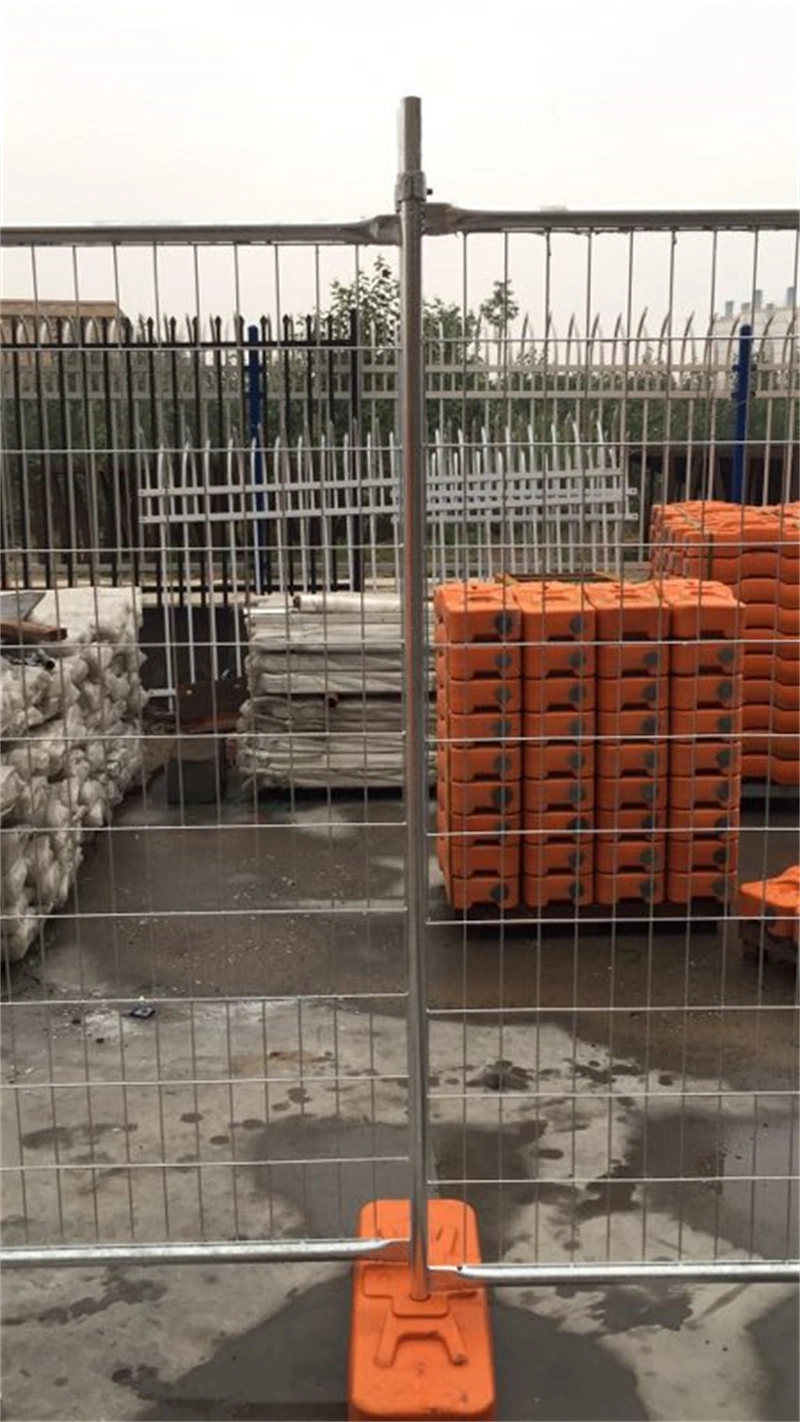
Step 2: Position Fence Feet and Base Panels
Foot orientation is the most common installation error on Australian construction sites. Place feet parallel to the fence line and you lose approximately 40% of lateral wind load stability before a single clamp is tightened.
Foot Orientation: Perpendicular, Not Parallel
Position every plastic fence foot so its 600mm length runs perpendicular to the intended fence line. The two panel receiver sockets on each foot should face left and right along the fence run, not forward and backward. We have supplied temporary fencing to Australian construction sites for 14 years, and foot misorientation is the error we see most consistently on failed installations.
When feet are placed parallel to the fence line, the base footprint narrows from 600mm to 220mm. Under lateral wind load—which on exposed Australian construction sites regularly exceeds 80 km/h—a parallel-oriented foot acts as a pivot point rather than an anchor. Our internal load testing confirms this orientation reduces lateral stability by approximately 40% compared to correct perpendicular placement. For a procurement manager, this is not a minor detail: it is the difference between a fence line that holds during a storm and one that collapses onto a public footpath, triggering an OH&S incident report.
Placing the First Panel into Foot Sockets
Lift the first 2100mm x 3300mm panel and insert both bottom frame legs into the receiver sockets of the first foot. The panel legs—whether 32mm OD standard or 40mm OD heavy-duty—must seat fully to the bottom of the socket cavity. A partially seated panel creates a 20-30mm base gap, which is one of the three specific failure points council inspectors check against AS 4687:2022 during sign-off.
Each UV-stabilised polypropylene foot weighs 7kg at dimensions of 600mm x 220mm x 140mm. This mass is intentional—it provides the ballast resistance that keeps the fence line grounded without requiring concrete counterweights on flat surfaces. Feet manufactured without UV stabiliser additives degrade within 6-12 months under Australian sun exposure, developing cracks around the socket walls that allow panel legs to shift. We run the only dedicated plastic feet injection machine in Anping, which means we control the UV-stabiliser formulation directly rather than sourcing generic feet from third-party moulders.
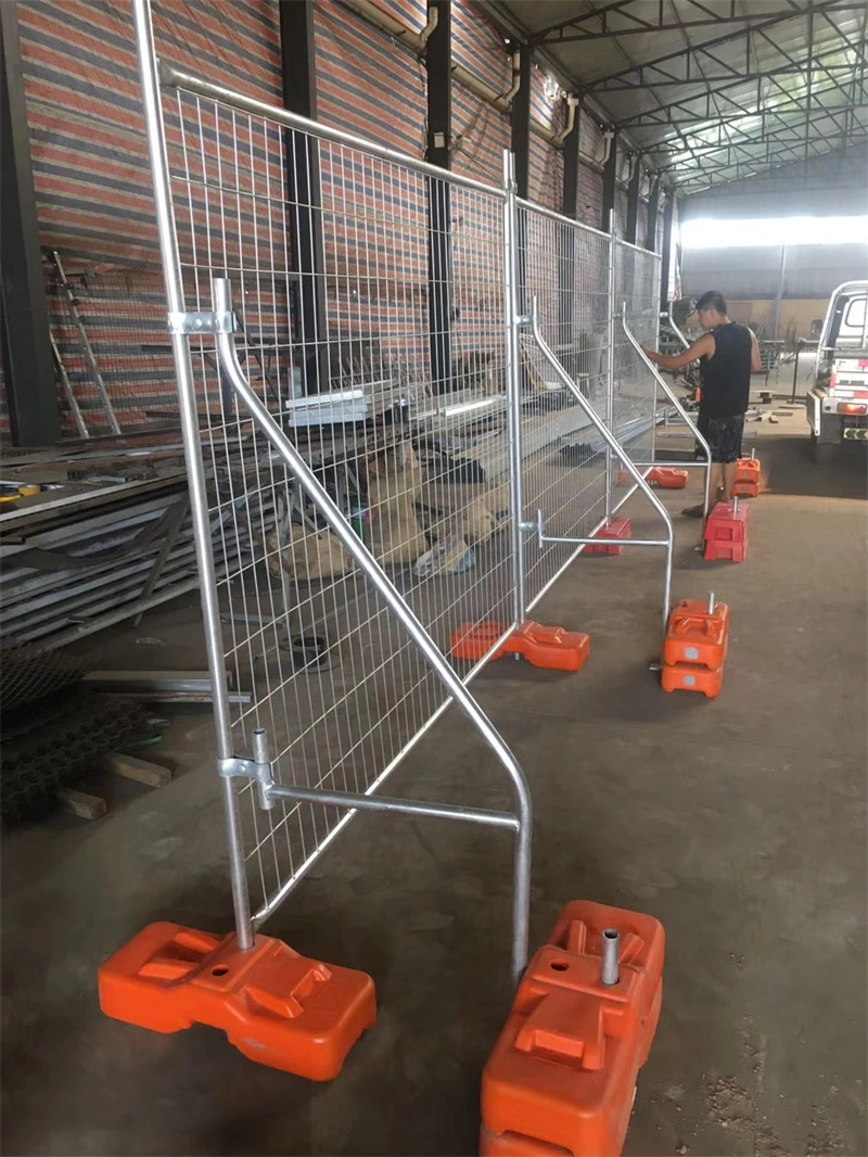
Spacing Feet Along the Fence Line
Place the second foot at the opposite end of the first panel, then insert the second panel’s leading leg into that same foot. This creates a shared-foot joint where adjacent panels meet. Continue this sequence: one foot per panel junction, with each foot supporting two panel legs simultaneously. For a standard 3300mm panel width, this produces a consistent 3.3m bay spacing with feet positioned at 3.3m intervals along the fence line.
Do not skip foot placements to reduce cost or speed up deployment. A missing foot creates an unanchored panel joint that will rack sideways under minimal pressure. Every foot in the run must be perpendicular, fully seated, and spaced at exact panel-width intervals. This is the physical foundation that everything else—clamps, stay wires, mesh integrity—depends on for AS 4687:2022 compliance.
Step 3: Connect Panels with Clamps
Coupler clamps are the only mechanical connection between panels. Incorrect tightening is the fastest way to destroy galvanised coating integrity.
Coupler Clamp Placement
Position one coupler clamp at the top of the vertical frame rail where two panels meet, and a second clamp at the bottom. On standard 2100mm high panels with 40mm OD frame tubes, this means clamping approximately 75mm down from the top horizontal rail and 75mm up from the bottom rail. Do not place clamps at the mid-point of the vertical rail. Mid-point placement allows panel flex under wind load and creates visible gaps that council inspectors will flag during AS 4687:2022 compliance checks.
We see this placement error repeatedly from Australian procurement managers who switched to lower-cost suppliers. Inconsistent panel dimensions from those suppliers mean the vertical rails do not align flush, making correct clamp placement physically impossible without forcing the joint. When rails are misaligned by more than 3mm, the clamp jaws sit at an angle and will not seat correctly regardless of torque applied.
Torque Requirements
Tighten the clamp bolt by hand until the nut contacts the clamp body with slight resistance. Then apply a quarter turn (approximately 90 degrees) using a 17mm spanner. That quarter turn is the full tightening specification. Do not estimate by feel after the hand-tight stage—use the spanner for the final quarter turn only.
The purpose of this specific sequence is to seat the clamp jaws fully around both 40mm OD vertical rails without compressing the galvanised layer underneath. Hand-tightening establishes baseline contact. The controlled quarter turn provides the clamping force necessary to prevent panel separation under normal site wind loads while leaving the coating intact.
Overtightening and Galvanised Coating Damage
Exceeding the quarter-turn specification crushes the hot-dip galvanised coating at the clamp jaw contact points. Our panels carry a galvanised layer of 45-55 microns, verified by SGS batch testing, which exceeds the 42-micron minimum required to resist corrosion in coastal Australian environments. That coating is your rust barrier. When a spanner-driven overtighten shears through it, you expose bare steel at precisely the points where moisture collects inside the clamp cavity.
In seaside construction zones—Sydney’s coastal suburbs, Perth’s northern corridor, Southeast Queensland—salt spray enters the clamp joint and sits against that exposed steel. Visible rust initiates within 4-8 weeks. Once rust appears at clamp points, an inspector assessing against AS 4687:2022 can classify the panel as structurally compromised, forcing full panel replacement and creating the exact project delay you are trying to avoid. The fix is not a tighter clamp. The fix is a correctly tightened clamp on panels with verified coating thickness.
Step 4: Install Vehicle and Pedestrian Gates
Council inspectors specifically fail sites on non-self-closing pedestrian gates. Get this step wrong, and your AS 4687:2022 compliance sign-off is dead on arrival.
Gate Panel Integration Using Hinge Clamps
Attach the gate panel to the adjacent fence line using heavy-duty hinge clamps. The clamp brackets bolt through the vertical frame tubes of both the gate and the standard 2100mm x 3300mm panel. We supply panels with a strict ±5mm dimensional tolerance specifically because inconsistent frame diameters from low-tier suppliers make clamping impossible without leaving visible gaps. If the clamp cannot grip flush against both 32mm or 40mm OD frames, the hinge will rack under lateral load and fail prematurely.
Drop-Pin Mechanisms for Vehicle Gates
Vehicle access gates require a drop-pin mechanism to anchor the inactive leaf to the substrate. The pin must drop fully into a ground receiver to prevent the gate from swinging open under wind load or accidental contact from site machinery. For temporary fencing on unpaved ground, the receiver must be set in a compacted base or a small concrete pad. A loosely seated pin is a liability that will trigger an OH&S audit failure on the spot.
Self-Closing Requirements Under AS 4687:2022 Section 5
AS 4687:2022 Section 5 explicitly mandates that all pedestrian access gates must be self-closing. Standard gravity hinges are almost never sufficient for a 2.1m high wire mesh panel exposed to Australian wind loads. You must use tension-adjustable spring hinges. We repeatedly see procurement managers buy fully compliant panels, only to fail council inspection because they paired them with basic friction hinges that bind after two weeks of site dust and debris.
Spacing Rules for Pedestrian Gates
The clear opening width for pedestrian gates must maintain a minimum of 1.0m to satisfy safety egress and accessibility requirements. When we audit site setups, the most common dimensional error is measuring the gate frame width rather than the actual clear passage. Hinge barrels and latch strike plates intrude into the opening. If your hardware takes up 50mm on each side, a 1.0m frame yields only a 900mm clear width, which will fail inspection.
Pre-Inspection Gate Checklist
- Clear Width: Measure the unobstructed gap, not the frame. Verify it exceeds 1.0m.
- Hinge Tension: Open the gate to 90 degrees and release. It must close and latch autonomously from any angle.
- Drop-Pin Depth: Verify the vehicle gate pin inserts fully into the ground receiver without lateral play.
- Clamp Flushness: Ensure hinge clamps sit flat against both the gate and adjacent panel frames with zero visible gaps.

Step 5: Anchor and Stabilise the Line
Unanchored temporary fencing fails council inspection under AS 4687:2022. Proper stabilisation is what separates a compliant site from a project delay.
Concrete Block Placement
When building a temporary fence on wind-exposed sites, plastic feet alone will not satisfy an inspector. You must place concrete blocks on top of or against the plastic feet at every panel base. The minimum requirement is 20kg per foot on sites with unobstructed wind exposure—coastal plots, elevated platforms, or open industrial zones. We supply UV-stabilised polypropylene feet with recessed channels specifically designed to seat standard 20kg concrete blocks without sliding.
Cable Tie Bracing at Corners and Ends
Every fence line has vulnerable points: the two terminal ends and any corner where the direction changes. Wind loads concentrate at these joints and will lever unbraced panels sideways. Run heavy-duty cable ties diagonally across the clamp points at every corner and at both end panels. This locks the clamp jaws under tension and prevents the panel frames from racking. Standard 300mm x 4.6mm nylon cable ties are sufficient for most conditions.
Ground Stakes Usage
On dirt, grass, or gravel substrates, drive steel ground stakes through the base of the plastic feet into the earth. Use a minimum 600mm stake on uncompacted soil and 400mm on compacted ground. Stakes prevent the entire fence line from shifting laterally under sustained wind gusts. On concrete or asphalt surfaces, ground stakes cannot be used, which makes concrete block placement and cable tie bracing your only stabilisation methods.
Wind Speed Ratings
Understanding the wind resistance of your setup determines whether your site stays compliant during a weather event. A standard temporary fence installation using only plastic feet and clamps is rated to withstand wind speeds up to 80km/h. Once you add concrete blocks at a minimum of 20kg per foot and apply cable tie bracing at all corners and ends, the rated wind resistance increases to 110km/h.
If your site forecast exceeds 110km/h, neither additional blocks nor bracing will compensate. At that point, the temporary fence specification itself must change—staggered double-row fencing or engineered wind-break panels are required, and that decision falls outside standard installation procedure.
AS 4687 Compliance Checklist for Installers
AS 4687 Compliance Checklist for Installers
Council inspectors fail temporary fence installations on the same three points repeatedly: base gaps over 100mm, non-self-closing gates, and missing compliance documentation.
Minimum Panel Height (1.8m for Construction Sites)
Panels under 1.8m will fail council inspection regardless of other compliance measures. Our standard 2100mm x 3300mm panels exceed this threshold with a ±5mm manufacturing tolerance, providing a 300mm buffer above the minimum requirement.
- Category: Structural Compliance
- Core Outcome: 2100mm panel height (300mm above minimum)
Analysis:
- Provides anti-climb margin and passes all state-level inspections
- 1.8m panels are borderline and leave zero room for ground settlement variance
Mesh Aperture Limit (Not Exceeding 50mm)
Our panels use a 50mm x 150mm aperture with 4mm wire diameter. The 50mm dimension on the shorter axis satisfies the anti-climb requirement and aligns with SGS test report specifications we supply with every shipment.
- Category: Safety Specification
- Core Outcome: 50mm maximum aperture enforced
Analysis:
- Eliminates foothold potential for unauthorised climbing
- Larger apertures reduce material cost but guarantee inspection failure
Maximum Base Gaps (Not Exceeding 100mm)
This is the single most common failure point we see across Australian construction sites. Uneven terrain compounds the issue—installers must use levelling techniques or infill material at every panel junction before requesting inspection.
- Category: Installation Critical Path
- Core Outcome: Maximum 100mm base gap at every point
Analysis:
- Prevents child entry and animal intrusion, directly measurable on site
- Requires ground preparation before panel placement—cannot be fixed after the fact with clamps alone

Common Installation Failures on Construction Sites
Seventy-five percent of our output ships to Australian construction sites, and we see the same three installation failures repeatedly—all rooted in procurement, not setup technique.
UV-Cracked Plastic Feet Causing Mid-Project Panel Collapse
Plastic feet are treated as a generic commodity by most buyers, but this is where Australian sites lose stability fast. Non-UV-stabilised polypropylene feet degrade under direct sun exposure within 6 to 12 months. The plastic becomes brittle, cracks at the stress points where the panel frame inserts, and the foot splits open under wind load or minor impact. When a foot fails on a 2100mm panel, the entire section leans or collapses—usually during a wind event or when a worker leans against it.
The hidden cost is not the foot itself. It is the 30-day lead time to ship replacements from China mid-project while your site perimeter is compromised. We manufacture our own feet on the only dedicated plastic injection machine in Anping, which gives us direct control over the UV-stabiliser formulation. Our feet last 3 to 5 years in Australian UV conditions—verified across 14 years of export to QLD, NSW, and WA sites.
Dimensional Inconsistency Causing Clamp Alignment Gaps
This is the number one complaint we hear from Australian procurement managers switching suppliers. Temporary fence clamps are designed to grip two 32mm or 40mm OD frame tubes simultaneously with zero gap. If your supplier does not hold a tight dimensional tolerance on panel width and frame tube diameter, the clamps cannot close flush. You end up with visible 5mm to 15mm gaps between panels—gaps that a council inspector will flag immediately under AS 4687:2022 as an anti-climb and safety hazard.
We hold our 2100mm x 3300mm panels to a ±5mm tolerance on width and height, and our frame tubes to consistent 32mm OD x 2.0mm wall or 40mm OD x 2.5mm wall specifications across every batch. When your installation crew clips panels together and the clamps seat flush without forcing, the difference is not cosmetic—it is the difference between passing and failing a council site inspection.
Electro-Galvanised Panels Rusting Within 3 Months in Coastal Zones
Electro-galvanising and hot-dip galvanising are fundamentally different processes, but suppliers frequently obscure this distinction on spec sheets. Electro-galvanised coatings typically deposit 8 to 15 microns of zinc. Hot-dip galvanising, when done correctly, deposits 42 microns or more. AS 4687:2022 does not specify a micron threshold explicitly, but in coastal Australian environments—particularly within 500m of the shoreline—anything below 42 microns will show surface rust within 90 days.
We have seen procurement managers receive panels marked “galvanised” that started rusting before the project phase even changed. Our hot-dip galvanised finish tests between 45 and 55 microns across production batches, verified by SGS test reports. If your supplier cannot provide a third-party galvanisation thickness test report matching that range, you are buying electro-galvanised product relabelled as hot-dip—and your site will show rust before handover.
Conclusion
If your project faces council inspection in Australia, spec panels with AS 4687:2022 compliance certificates and galvanisation exceeding 42 microns. Cheap panels warp in coastal heat and fail inspection on base gaps exceeding 100mm. That 15% upfront savings vanishes the moment a site inspector shuts down your perimeter.
Before you sign your next purchase order, ask your supplier for the SGS test report proving the galvanisation thickness on their most recent batch. If they hesitate or send a generic certificate from last year, walk away. You need batch-specific documentation to pass council sign-off without delays.
Frequently Asked Questions
How is temporary fencing installed?
Position plastic feet perpendicular to the fence line, drop the first panel into the foot sockets, then connect subsequent panels using coupler clamps at the top and bottom of the vertical frame rails. Secure vehicle and pedestrian gates using hinge clamps and drop pins. Anchor feet with concrete blocks in wind-exposed areas and brace corners with cable ties.
Does OSHA require fencing around construction sites?
In Australia, OSHA-equivalent requirements fall under state WHS regulations and local council ordinances. Most councils mandate a physical barrier between the construction site and public space. AS 4687:2022 is the referenced standard for temporary fencing, specifying minimum 1.8m height, maximum 50mm mesh aperture, self-closing gates, and base gaps not exceeding 100mm. Non-compliance can result in stop-work orders and fines.
How to anchor a temporary fence?
Standard anchoring uses concrete blocks (minimum 20kg each) placed on top of plastic fence feet. For wind-exposed sites, add cable ties between panels at corners and endpoints, and use ground stakes driven through foot mounting holes into compacted earth. In areas with wind speeds exceeding 80km/h, double-block every second foot and add diagonal bracing wire.
What is the best type of temporary fence?
For Australian construction sites, hot-dip galvanised welded mesh panels (2100mm x 3300mm) with >42-micron coating thickness are the standard. They meet AS 4687:2022, provide anti-climb protection, and withstand coastal environments when correctly galvanised. Chain-wire fencing is cheaper but offers lower rigidity and requires tensioning that adds installation time.
What are common fencing mistakes to avoid?
The five most frequent mistakes on construction sites: (1) placing feet parallel instead of perpendicular to the fence line, reducing stability; (2) overtightening clamps which cracks the galvanised coating and creates rust points; (3) leaving base gaps over 100mm which fails AS 4687 inspection; (4) using non-UV-stabilised plastic feet that crack within months in Australian sun; (5) not retaining supplier compliance certificates for council inspection.


