 Skip to content
 Steel Fence Engineering Essentials
- Accurate wind load calculation using local building codes, such as ASCE 7, is the foundational step that defines all subsequent design decisions, including post sizing and foundation requirements.
- A successful and durable installation depends on a tailored foundation design, which must be based on a thorough analysis of local soil conditions to ensure long-term stability and full code compliance.

Overview of Steel Fence Structural Engineering
The structural engineering of a steel fence system is a specialized discipline that extends far beyond simple boundary demarcation. It involves a rigorous application of civil and structural engineering principles to ensure a fence can safely withstand environmental loads, primarily from wind, over its entire service life. Key considerations in this field include the precise calculation of wind-induced forces, the design of robust foundations anchored in specific soil types, and the formal certification process required for regulatory approval. Understanding these interconnected elements is paramount for any engineer, contractor, or project manager involved in designing and specifying commercial, industrial, or high-security steel fencing projects.
Unlike conventional building structures, which often present large, contiguous surfaces to the wind, steel fences introduce unique geometric complexities. The specific properties of steel—its high strength-to-weight ratio—allow for slender and elegant designs. However, this slenderness makes individual posts and panels highly susceptible to bending and vibration. Furthermore, the geometry of a fence, whether it’s a solid panel, a perforated screen, or a series of vertical pickets, critically influences how it interacts with wind. A solid barrier will experience the full force of the wind pressure, whereas a porous or picket-style fence creates complex turbulence and aerodynamic effects that must be carefully analyzed, as they can induce dynamic oscillations and concentrated stress points not seen in typical building envelopes.
Importance of Structural Engineering for Fences
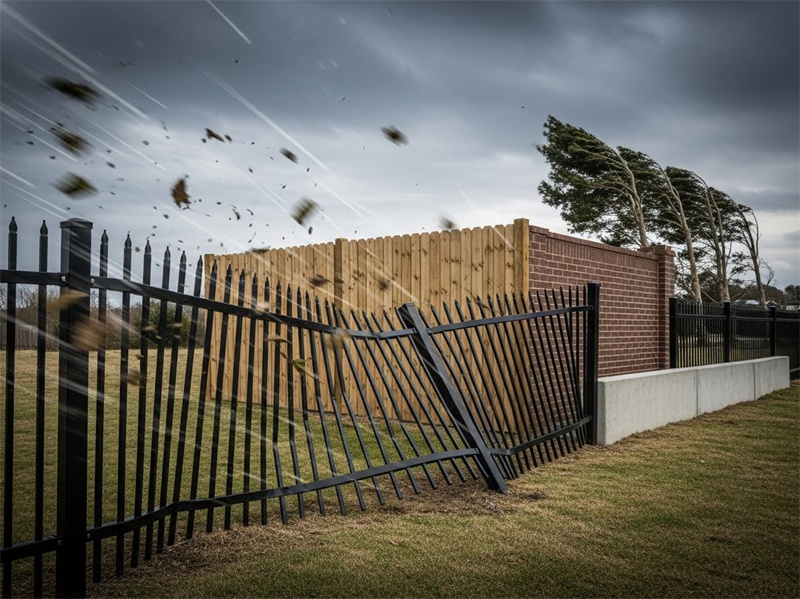
The role of structural engineering in the design of steel fences is fundamentally about ensuring public safety and long-term asset durability. A properly engineered fence is meticulously designed to resist predictable environmental forces like strong winds. This foresight prevents catastrophic failure that could lead to property damage, injury, or even death.
The consequences of inadequate engineering are severe and multifaceted, creating significant risks. For example, under significant wind stress, poorly designed posts can bend permanently or snap, while improperly sized foundations can lead to the entire fence system overturning. This failure creates immediate safety hazards from falling debris and also compromises the security of the perimeter it was meant to protect.
The unique challenge posed by wind loads on vertical steel fence members cannot be overstated. These slender elements act like cantilever beams anchored in the ground, and wind pressure subjects them to significant bending moments and shear forces. Without a precise understanding of these forces, as dictated by standards like the ASCE 7 (Minimum Design Loads for Buildings and Other Structures), designers risk specifying posts that are too weak or spaced too far apart, leading to excessive deflection or outright failure. Consequently, regulatory bodies and local building authorities increasingly mandate that structural calculations, signed and sealed by a licensed professional engineer, accompany permit applications for any fence over a certain height, ensuring that these life-safety considerations are formally addressed and documented.
Core Components: Wind Loads, Foundations & Certification
A successful steel fence project hinges on the seamless integration of three core structural components: wind load analysis, foundation design, and engineering certification. The process begins with a detailed calculation of the anticipated wind loads for the specific project location. This analysis informs the necessary strength and stiffness of the fence posts and determines their maximum allowable spacing. These forces are then transferred from the posts into the ground, making foundation design the next critical step. This involves sizing concrete footings and determining embedment depths based on the calculated overturning moments and the site’s specific soil properties.
These two technical components—wind load calculations and foundation design—are intrinsically linked. A higher wind load necessitates beefier posts, which in turn demand larger and deeper foundations. Finally, the entire design package must be validated through professional engineering certification. A licensed engineer reviews the structural calculations, drawings, and specifications to confirm they meet all applicable building codes and safety standards. This certification provides assurance to the client, the contractor, and the permitting authority that the fence is designed to perform safely and reliably, forming a complete, structurally sound system from the top of the fence to the bottom of its foundation.
Wind Load Calculations for Steel Fencing
At the heart of all resilient fence design lies the accurate calculation of wind loads. On a recent coastal project I consulted on, the initial design tragically underestimated the topographic effects of a nearby bluff. The standardized wind speed data wasn’t adjusted for this feature, and the initial calculation for the Kzt factor was non-compliant. A secondary review caught this error, forcing a redesign with larger posts and deeper foundations. This experience underscores a critical lesson: a formula is only as good as the data fed into it, and overlooking localized site conditions as defined by codes like ASCE 7 or Eurocode can lead to a spec failure before a single post is even installed. Proper calculation is not an academic exercise; it’s the primary determinant of a fence’s structural integrity.
Before diving into the equations, it’s crucial to understand the physics of how wind interacts with a fence. Unlike a solid building wall, a fence is a relatively thin, often perforated or porous, structure. Wind flowing around and through the fence components creates complex pressure differentials and turbulence. Positive pressure builds on the windward face, while negative pressure (suction) occurs on the leeward side. For perforated or picket fences, the wind jets through the openings, creating turbulence that can induce vibration and fatigue. Furthermore, wind is not a static force. Gusts can cause a sudden, sharp increase in load, which means the structure must be designed to handle these dynamic peak forces, not just the average wind speed.
Wind Speed and Exposure Categories
The first step in any wind load calculation is to determine the basic wind speed for the project’s geographic location. This critical piece of data is obtained from regional code maps, such as those provided in ASCE 7, or from local meteorological databases. This value represents the 3-second gust speed at 10 meters above the ground for a specific risk category and is typically expressed in miles per hour (mph) or meters per second (m/s). This base value, however, is only the starting point and must be modified by several factors to accurately reflect site-specific conditions.
One of the most important modifiers is the Exposure Category, which accounts for the roughness of the surrounding terrain. Engineering codes define several categories, with the most common being B, C, and D. Exposure B applies to urban and suburban areas or wooded terrain where numerous closely spaced obstructions can slow the wind. Exposure C is for open terrain with scattered obstructions, such as flat, open country or grasslands. The most severe, Exposure D, is reserved for flat, unobstructed areas directly exposed to wind flowing over large bodies of water, such as coastlines and shorelines. Choosing the correct exposure category is critical, as moving from Exposure B to D can significantly increase the calculated design wind pressure.

| Exposure Category | Terrain Description | Typical Locations |
|---|---|---|
| B | Suburban/wooded areas | Residential neighborhoods |
| C | Open terrain with scattered obstacles | Farmland, open country |
| D | Coastal or flat unobstructed areas | Seaside cliffs, large bodies of water nearby |
Calculating Design Wind Pressure
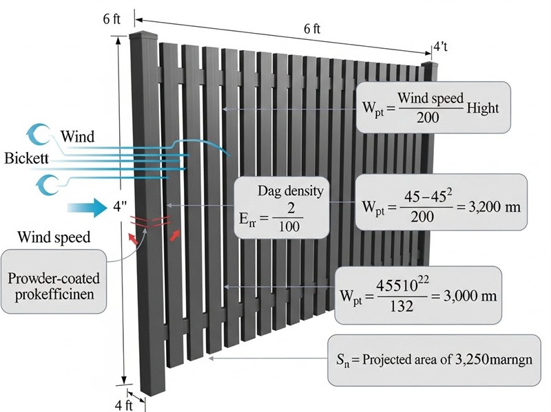
Once the basic wind speed and exposure category are established, the design wind pressure (p) can be calculated. The formula specified in many international codes, including Eurocode, is often presented as p = 0.6 * V² * Kz * Ke * Kzt * Kd (when V is in m/s). Each term in this equation plays a distinct role in refining the raw wind speed into a site-specific pressure. Here, ‘V’ is the basic wind speed, while the ‘K-factors’ adjust this value for various environmental conditions. This calculation provides the force per unit area that the fence structure must resist.
Let’s break down the adjustment factors. Kz is the velocity pressure exposure coefficient, which accounts for the height of the fence and the roughness of the terrain (derived from the Exposure Category). Ke is the gust effect factor, which increases the load to account for the dynamic effect of gusts on a flexible structure. Kzt is the topographic factor, which addresses wind speed-up effects caused by hills, ridges, and escarpments. Finally, Kd is the wind directionality factor, which accounts for the reduced probability that the maximum wind will come from a direction that is most critical to the structure. For thin vertical members like fence panels, an additional pressure coefficient (Cp) is often applied, with typical values ranging from -0.7 to -0.9, representing the suction effect on the leeward face. To find the total force on a panel, this final pressure value is simply multiplied by the projected area of the panel.
| Factor | Description | Typical Value Range/Example |
|---|---|---|
| V | Basic Wind Speed (m/s) | 30 m/s (example) |
| Kz | Exposure Height Factor | 1.0-1.3 |
| Ke | Gust Effect Factor | 0.85-1.15 |
| Kzt | Topographic Factor | 1.0-1.2 |
| Kd | Wind Directionality Factor | 0.85 |
Interpreting Wind Load Effects on Fence Structure
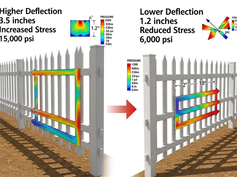
The calculated wind pressure is not the end of the analysis; it’s the input. This distributed load creates two critical effects that the fence posts must resist: shear and overturning moment. Shear is the horizontal force at the base of the post that tries to slice it off at ground level. The overturning moment is the rotational force, created by the wind pressure acting on the panel area at a height above the ground, which tries to tip the post over. The post and its foundation must be designed to safely resist both of these forces simultaneously.
Beyond pure strength, the design must also consider serviceability. A fence that bends excessively in the wind, even if it doesn’t break, is often considered a failure. To prevent this, engineers check the design against allowable deflection limits. A common serviceability limit for fence posts is L/200, where ‘L’ is the height of the post. This means a 4-meter (4000 mm) tall post should not deflect more than 20 mm at its top under design wind loads. These strength and serviceability requirements directly dictate the necessary post size and material thickness, the maximum allowable spacing between posts, and the specific details of the anchorage system that connects the post to its foundation.
Fence Post Spacing and Structural Requirements
Once the wind load per square meter is known, the engineer can determine the optimal spacing for the vertical fence posts. This decision is a crucial balancing act between material cost, aesthetics, and structural performance. While it might seem economical to space posts as far apart as possible, doing so dramatically increases the load each individual post and its foundation must bear. This concentration of force necessitates larger, heavier, and more expensive posts and foundations to manage the increased bending stresses and prevent excessive deflection, often negating the initial cost savings.
The underlying principle here is the direct relationship between post spacing, the post’s section modulus, and the resulting lateral deflection. The section modulus is a geometric property of a post’s cross-section that measures its resistance to bending. When posts are spaced farther apart, each one is responsible for a larger tributary area of fence panel. This larger area collects more wind, imparting a greater total force and a higher bending moment on the post. To keep deflection within acceptable limits (like L/200), a post under higher load must have a significantly larger section modulus. Conversely, by tightening the spacing, the load is distributed across more posts, reducing the stress on each one individually. This allows for the use of more slender, cost-effective post profiles while still maintaining the structural integrity and serviceability of the entire fence system.
Determining Post Spacing from Wind Loads
In the fencing industry, post spacing commonly ranges from 1.8 meters (approx. 6 feet) to 3 meters (approx. 10 feet), but these are merely guidelines. The actual maximum allowed spacing is a calculated value, not a rule of thumb, and it varies significantly based on fence height, panel type, and the design wind pressure for the region. The calculation begins by determining the total wind force acting on a single bay of fencing (the area between two posts). This force is then used in beam bending equations to determine the resulting stress and deflection in the post. The engineer then adjusts the spacing until both the stress and deflection are within the allowable limits defined by the building code and the material’s properties.
The post’s material properties and cross-sectional geometry are critical inputs for this calculation. The moment of inertia (a measure of a shape’s resistance to bending) and the section modulus of the post’s cross-section are key parameters. For example, to calculate the maximum spacing for a 2.4-meter-tall fence in a 130 km/h wind zone, an engineer would first calculate the wind pressure. They would then assume a standard post spacing, calculate the bending moment, and check if the resulting stress exceeds the steel’s yield strength or if the deflection exceeds L/200. If it does, the spacing must be reduced until both criteria are met, establishing the final, engineered spacing for the project.
Post Sizing and Material Considerations
Post sizing is directly derived from the wind load and spacing calculations. For moderate wind conditions and standard fence heights (e.g., up to 2.4 meters), a 100mm x 6mm rectangular hollow section (RHS) steel post might be sufficient. However, for taller fences, higher wind regions, or fences with solid infill panels that catch more wind, the specifications might call for larger sections like a 150mm x 8mm post or even a small I-beam. The goal is to select a profile with the necessary section properties to resist bending stresses without being over-engineered, which would add unnecessary cost.
Beyond simple strength, the choice of material and its protection are vital for long-term performance. Steel offers excellent strength, but it is also susceptible to fatigue if subjected to constant, repetitive loading, such as wind-induced vibrations. Engineers may consider this in high-wind environments where cyclic loading is common. Most importantly, since fences are permanently exposed to the elements, corrosion protection is non-negotiable. Galvanizing, powder coating, or duplex systems (galvanizing plus powder coating) are essential to prevent rust, which not only degrades the fence’s appearance but can also reduce the post’s effective cross-sectional area, compromising its structural capacity over time. Proper corrosion protection is a cornerstone of a durable and safe installation.
Foundation Design for Steel Fence Posts
A fence post is only as strong as its foundation. I was once called to inspect a perimeter fence at a logistics park built on reclaimed land. Despite the posts themselves being correctly specified, the contractor had used a “standard” footing design without a site-specific soil report. Within two years, differential settlement caused several sections of the fence to lean precariously. This costly remediation effort could have been completely avoided by understanding a fundamental principle: the foundation must be designed not just for the fence, but for the ground it stands on. The soil’s behavior—its ability to bear weight and resist lateral forces—is the ultimate arbiter of stability.
The design of a fence foundation is a direct response to the forces calculated in the wind load analysis. The foundation’s primary jobs are to anchor the post against the overturning moment caused by wind and to transfer all vertical loads (the weight of the post and panel) into the ground without excessive settlement. The principles of soil mechanics govern this interaction. Key concepts include bearing capacity, which is the soil’s ability to support the downward load without failing, and passive soil resistance, which is the horizontal resistance the soil provides as the footing tries to rotate or slide. A properly designed footing is sized and shaped to mobilize enough of this passive resistance and stay within the soil’s bearing capacity limits, ensuring the fence remains upright and stable for decades.
Soil Condition Analysis for Foundations
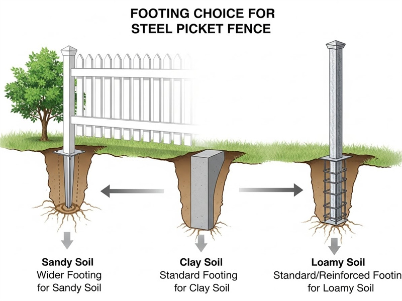
The first step in any foundation design is to understand the ground conditions. Soils are broadly classified into types like sandy, clay, silt, or rocky, each with distinct geotechnical properties. Sandy and gravelly soils generally drain well and offer good bearing capacity, while clay soils can be problematic, as they can shrink or swell dramatically with changes in moisture content. Poorly compacted fill or organic soils may offer very little structural support. For most significant fencing projects, especially those requiring permits, a professional soil analysis is essential.
This analysis, often presented in a geotechnical report, provides the critical data needed for foundation design, most notably the soil’s allowable bearing capacity. According to Geotechnical Engineering Manuals, this value can range from over 600 kN/m² for hard rock to less than 75 kN/m² for soft clays and silts. Poor soil conditions, such as a low bearing capacity or a high water table, will necessitate a more robust foundation design. This might involve wider footings to spread the load over a larger area, deeper embedment to reach a more stable soil layer, or even specialized solutions like helical piles. In areas with significant challenges, commissioning a formal soil report from a geotechnical engineer is not an expense—it’s a critical investment in risk mitigation.
Quality Metal Fences Direct from Our Factory
Get reliable, international-standard fencing with fast sample delivery and expert support. Choose from steel picket fences, temporary fencing, and more—all at competitive factory prices.
Footing Types and Dimensions
For steel fences, the most common foundation types are reinforced concrete spread footings and concrete-filled steel pipe piles (caissons). A spread footing is essentially a concrete block excavated into the ground, which provides a large base to resist overturning and distribute the load. A typical design for a 100 mm post might specify a footing width of 300–500 mm. The size of the footing is calculated based on the combined loads—the vertical dead load of the fence, the horizontal shear from the wind, and the critical overturning moment. A larger overturning moment requires a wider or deeper footing to generate enough resisting force.
To handle the tensile stresses that develop within the concrete as it resists bending, these footings are almost always reinforced with a steel rebar cage. For a standard fence post footing, a cage constructed from 10-mm rebar is common, placed strategically within the formwork before the concrete is poured. The concrete itself is also specified by its compressive strength, with a C25/30 mix (25 MPa strength) being a common minimum for structural applications. This combination of concrete and steel in the footing design creates a composite member capable of withstanding all anticipated forces and transferring them safely into the surrounding soil.

| Post Size | Footing Width (mm) | Embedment Depth (mm) | Reinforcement |
|---|---|---|---|
| 100 x 6 mm | 300-500 | 600-900 | 10 mm rebar cage |
| 150 x 8 mm | 400-600 | 800-1200 | 12 mm rebar cage |
Embedment Depth Requirements
The embedment depth of a footing is arguably as important as its width. The primary function of the depth is to provide sufficient passive soil resistance to counteract the overturning moment from the wind. As the wind pushes on the fence and tries to rotate the post and footing, the face of the footing pushes against the soil in front of it, and the back face pulls away from the soil behind it. The deeper the footing, the greater the volume of soil mobilized to resist this rotation. The required embedment depth is calculated to ensure that this resisting moment from the soil is significantly greater than the overturning moment from the wind, providing a robust factor of safety.
Typical embedment depths for fence posts might range from 600 mm to over 1200 mm, depending on the loads and soil conditions. For a typical sandy soil with a bearing capacity of approximately 150 kN/m², a 900 mm deep footing might be sufficient for a standard 2.4m fence. However, in softer clay, this depth might need to be increased to 1200 mm or more to achieve the same level of resistance. Additionally, in colder climates, the base of the footing must be placed below the local frost depth. This prevents frost heave—a phenomenon where freezing soil expands and lifts the foundation, which can damage the fence and compromise its structural integrity.
Engineering Certification and Permit Applications
In the world of construction, an uncertified structural design is little more than a set of suggestions. The process of engineering certification transforms a design from a theoretical exercise into a legally and professionally accountable document. This formal validation is not merely a bureaucratic hurdle; it is a critical checkpoint for risk management that enhances safety, ensures legal compliance with building codes, and provides essential liability protection for the property owner, the contractor, and the design engineer. For structural elements like tall steel fences, which can pose a significant public hazard if they fail, certification is the ultimate expression of professional due diligence.
The regulatory framework governing fences can vary dramatically by jurisdiction. As noted in recent industry analyses, some countries like Australia have specific national standards for certain fence types (e.g., AS 4687 for temporary fencing), while others, like Canada, rely on a patchwork of provincial OH&S codes and municipal bylaws. This complexity underscores the value of certification. It demonstrates that a qualified professional has navigated the specific local requirements—citing relevant publications from the local Building Code Authority—and has affirmed that the design is safe and compliant. Without this stamp of approval, a project can face costly delays, re-work orders, or outright rejection from permitting authorities.
Certification Requirements for Steel Fences
In many jurisdictions, any fence exceeding a certain height—often 1.8 to 2.0 meters—is legally classified as a “structure,” which mandates a formal building permit for construction. To secure this permit, project proponents must submit certified engineering documents that definitively prove the design’s safety and regulatory compliance. The required documentation is comprehensive, forming a complete package for review by authorities. This package typically includes detailed structural calculations for wind loads, specific construction drawings, and foundation plans tailored to the site’s unique geotechnical conditions.
The certifying engineer assumes professional liability for the design’s safety and adequacy. This is a significant ethical and legal responsibility. Common reasons for permit rejections are often linked to incomplete or unclear documentation, such as failing to specify the grade of steel, omitting rebar details in the footings, or using a generic wind load value that doesn’t account for local topography. A thorough and professional engineering certification process anticipates these requirements and delivers a comprehensive package that leaves no room for ambiguity, ensuring a smooth path to approval.
Preparing Engineering Documentation
The preparation of engineering documents for a permit application must be clear, concise, and meticulously aligned with the relevant standards. The structural calculation report is the cornerstone of the submission. It should methodically walk the plan reviewer through the entire design process, starting with the source of the basic wind speed, a clear statement of all K-factors and coefficients used, and the resulting design pressure. It must then show the calculations for post stress, deflection, and foundation overturning and bearing pressures, with each step referencing the specific clause in the applicable code (e.g., “per ASCE 7-16, Section 27.3.2”).
All drawings must be stamped or sealed by a licensed professional engineer registered in the state or province where the project is located. This seal is the engineer’s legal attestation that the design conforms to professional standards and all applicable regulations. A best practice is to include a submission checklist in the package, verifying that all required elements are present: sealed drawings, a sealed calculation report, soil report (if required), and product specification sheets for the steel and concrete. This level of organized and precise engineering documentation demonstrates professionalism and greatly streamlines the review process for busy building department officials.
Advanced Topics: Soil-Dependent Foundation Design & AI Monitoring
While standard foundation designs work for typical soil conditions, the frontier of fence engineering involves solving for challenging sites and leveraging new technology for asset management. As project sites become more complex, engineers face poor ground conditions that render conventional footings inadequate. Simultaneously, the rise of IoT and artificial intelligence is creating new possibilities for real-time performance monitoring, shifting the industry from a reactive to a predictive maintenance model.
The most promising development is the integration of smart sensor technology with AI-driven analytics. Imagine a high-security fence at a critical infrastructure facility equipped with strain gauges, accelerometers, and anemometers. These sensors can capture real-time data on wind speeds, gust effects, and the corresponding stress and vibration in the fence posts. This data stream can be fed into an AI algorithm that learns the fence’s normal response patterns. This system could then detect anomalies, predict potential fatigue failures before they occur, and issue automated maintenance alerts, revolutionizing how we ensure the long-term resilience and safety of these essential structures.
Foundation Design for Challenging Soils
Designing foundations for challenging soils like soft clays, expansive soils, or poorly compacted urban fill requires a specialized approach. In expansive clay soils, which swell when wet and shrink when dry, standard shallow footings can be lifted and shifted, destroying fence alignment. Here, solutions may include designing a “floating” foundation isolated from moisture changes or using deeper caissons or piles that anchor the fence in a more stable soil stratum below the zone of moisture fluctuation. For very soft or marshy soils with high water tables, piled foundations, such as driven steel piles or helical anchors, may be the only viable option to transfer loads to a deeper, competent bearing layer.
In these complex scenarios, close collaboration with a geotechnical engineer is indispensable. They may recommend geotechnical solutions such as soil stabilization, where additives like lime or cement are mixed into the soil to improve its strength and stiffness, or the use of geotextile fabrics to improve drainage and load distribution. A case study might involve a site with poorly compacted fill where the solution was to over-excavate the weak soil and replace it with engineered, compacted gravel before constructing the footings. Such site-specific adaptations are the hallmark of advanced foundation engineering, ensuring long-term performance where standard designs would fail.
Harnessing AI and Sensors for Wind Load Monitoring
The next frontier in structural security is real-time monitoring through a network of intelligent sensors. Emerging technologies allow for inexpensive wireless sensors to be placed directly onto fence posts to measure wind speed and structural response. This data provides an unprecedented, high-fidelity picture of a fence’s actual performance, a significant leap beyond theoretical design loads.
This live data stream becomes incredibly powerful when paired with AI algorithms. An AI monitoring system can be trained to analyze these loading trends, identify patterns that may indicate the onset of fatigue damage, or detect unusual vibrations that could signal a loosening foundation. In the event of an extreme weather event, the system could provide immediate alerts to facility managers if wind loads are approaching or exceeding the design limits, enabling proactive safety measures. For long-term asset management, this data provides invaluable insights for optimizing maintenance schedules and can even inform the design of more resilient and efficient fence systems in the future.

Quality Metal Fences Direct from Our Factory
Get reliable, international-standard fencing with fast sample delivery and expert support. Choose from steel picket fences, temporary fencing, and more—all at competitive factory prices.
Conclusion: Steel Fence Engineering Essentials
The structural integrity of a steel fence is not a matter of chance; it is the product of deliberate and precise engineering. A methodical approach from concept to installation ensures these structures can withstand environmental forces and fulfill their security functions for decades. Ultimately, the process is a chain of dependent decisions where each link must be as strong as the last to guarantee system integrity.
- Structural engineering is the fundamental practice that ensures steel fences can safely resist wind loads and maintain long-term serviceability, preventing failure and protecting assets and public safety.
- Precision is paramount. Accurate wind load calculations based on local codes, coupled with correctly engineered post spacing and a foundation design meticulously tailored to site-specific soil conditions, are the crucial ingredients for success.
- Professional engineering certification is the final, indispensable step that safeguards the project against liability, ensures full regulatory compliance, and provides all stakeholders with validated assurance of quality and safety.
- Looking forward, the adoption of advanced technologies like AI-powered structural health monitoring holds immense promise for creating the next generation of resilient, self-aware fence structures.
For any organization undertaking a significant steel fence project, the message is clear: engage with licensed structural and geotechnical engineers early in the process. Their expertise is not a cost center but a critical investment in resilience, safety, and long-term value. By embracing both time-tested engineering principles and innovative new technologies, you can future-proof your perimeter infrastructure against the challenges of tomorrow.
Frequently Asked Questions
How do I calculate wind loads for a steel fence?
To calculate wind loads, you must first obtain the basic wind speed for your specific location from local building codes (like ASCE 7). Then, you apply adjustment factors for the site’s exposure category (terrain roughness), height, topography, and wind directionality using the formula p = 0.6 V² Kz Ke Kzt Kd. This calculated pressure is then multiplied by the fence panel’s surface area to find the total horizontal force the structure must resist.
What is the recommended embedment depth for steel fence posts?
There is no single recommended depth; it must be calculated for each project. The depth is determined by the soil’s bearing capacity and the need to resist the overturning moment from wind. It must be deep enough to mobilize sufficient passive soil resistance to prevent tipping. While typical depths in stable sandy soil may range from 600-900 mm, this must be adjusted for weaker soils, higher wind loads, and local frost depth requirements to prevent heave.
Why is engineering certification required for steel fence permits?
Engineering certification is required to formally verify that the fence design is structurally safe and compliant with all applicable building codes and standards. A licensed engineer’s stamp provides legal and professional accountability, assuring the permitting authority and the owner that the fence has been designed to withstand predictable environmental loads like wind and will not pose a public safety hazard. It is a critical step for risk management and liability protection.
How does soil type affect fence foundation design?
Soil type is a critical factor because its properties dictate the size and depth of the foundation. The soil’s bearing capacity determines how much weight it can support, influencing the footing’s width. Its passive resistance affects the footing’s ability to resist overturning forces. For example, soft clay or loose sand has a much lower bearing capacity than dense gravel or rock, requiring significantly larger footings and deeper embedment to achieve the same level of stability.
Can AI technology be used in monitoring steel fences?
Yes, AI is an emerging technology in this field that enhances safety and resilience. By combining physical sensors on the fence with AI algorithms, it is possible to monitor the structural response to wind in real time. This system can analyze performance data, predict failures, issue alerts during extreme weather, and optimize maintenance schedules.


